Boolean logic
Boolean algebra and logic gates
In the 1840s, English mathematician George Boole developed an algebra (a set of operators and laws) for variables that can have just two states – true and false. Thus, a Boolean value is equivalent to one bit:
   False = 0 = off
   True  = 1 = on
The operators defined by Boole are pervasive throughout all of computing. You may have encountered them in doing library or other database searches. The ones we’ll consider are:
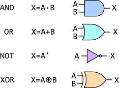
The table illustrates both the algebraic notation and the circuit diagram notation. The elements of circuit diagrams are called gates, as in “AND gate” or “XOR gate.”
The behavior of these operators can be defined by truth tables:
    A   B     A·B     A+B     A'     A⊕B
    0   0      0       0      1       0
    0   1      0       1      1       1
    1   0      0       1      0       1
    1   1      1       1      0       0
Combinational circuits
We combine the gates into combinational circuits to achieve various effects. For example, the algebraic expression X = A·B + A·C corresponds precisely to the following circuit diagram:
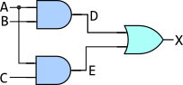
and we can discover its effect by completing the truth table:
    A   B   C   D=A·B   E=A·C   X=D+E
    0   0   0    0       0       0
    0   0   1    0       0       0
    0   1   0    0       0       0
    0   1   1    0       0       0
    1   0   0    0       0       0
    1   0   1    0       1       1
    1   1   0    1       0       1
    1   1   1    1       1       1
Exercise: Try drawing the circuits and the truth tables for X=(A·B)' and for X=A'+B'. They should produce the same result for the inputs A and B. This is one of DeMorgan’s Laws.

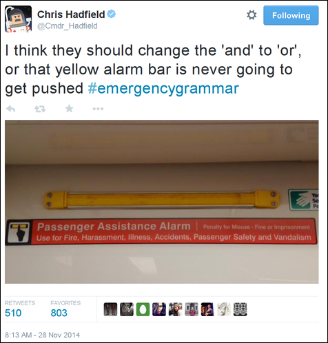
@secboffin on Twitter
Sequential circuits
We’ll just look at the S-R (NAND) latch.
- Flip Flops, Latches & Memory Details [8:53] from Computerphile
Logisim software
This section refers to a program called Logisim, which should run on any platform with a Java Runtime Environment. If you get the “unidentified developer” error on a Mac, go into System Preferences » Security and look for the button that says Open Anyway.

Once you open Logisim, there are a few tools you should familiarize yourself with.
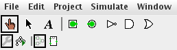
The ‘hand’ tool (leftmost on the toolbar) allows you to turn inputs on and off. The ‘arrow’ tool (next to it) allows you to place components onto the grid, move them around, and wire them together.
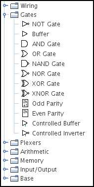
In the side-bar, the main components we’ll be using are in the Gates section, but there’s also the Pin (under Wiring) and the LED (under Input/Output).
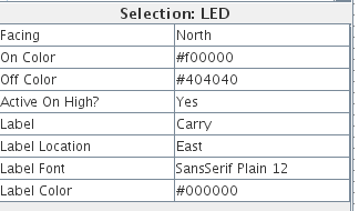
When you have a component selected, its properties appear in the lower left of the screen. You can use these to create a label for your pins and LEDs.
- The 3-bit adder circuit I did in class.
Further exploration
- Video: Building a half-adder using dominoes, with Matt Parker and Numberphile
- Video: The big domino adder, demonstrated at the Manchester Science Festival, UK
@Cmdr_Hadfield on Twitter