Computer architecture
![]()
These are notes-in-progress. Incomplete segments are marked with “TODO.”
Once we can arrange logic gates into circuits to perform arithmetic and retain memory, we are close to being able to build a full computer. But what additional components are needed, and how should they be organized?
1 Turing Machine
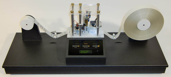
In 1936, British mathematician Alan Turing proposed a device that has come to be known as the Turing Machine. The idea was to have a mechanical reel-to-reel tape onto which symbols could be written, erased, and rewritten. In modern terminology, the tape represented input, output, and memory. The control unit of the machine would examine some current position on the tape, and based on the symbol there and its internal state, it could do any of the following:
- Move the tape one position to the left
- Move the tape one position to the right
- Erase the symbol at the current position
- Write a symbol at the current position
The proposal was mostly a thought experiment – it wasn’t necessarily intended to be a blueprint for the design of an actual computer. But Turing sought to prove things about what can be computed by any sort of person or device. So there was an analogy of a human mathematician working to prove or calculate something by writing symbols on paper.
Turing argued that the two-dimensional nature of paper was not essential to the calculation, so we could turn it into a long strip of paper instead. Furthermore, he argued that the wide variety of symbols used in mathematics were not essential either, as they could be encoded using just a few symbols (as we covered in the unit on text encoding).
The control unit would use circuitry representing a decision table
to determine what operations to perform under which conditions. As we
said before, it relied on a notion of an internal state. Only a
finite number of states would be allowed, and we can specify them
either using a table or a state diagram, as follows. (The symbol B
represents a blank spot on the tape.)
| Current state | Current symbol | New state | New symbol | Move to |
|---|---|---|---|---|
S0 |
0 |
S0 |
0 |
Right |
S0 |
1 |
S0 |
1 |
Right |
S0 |
B |
S1 |
B |
Left |
S1 |
0 |
S0 |
1 |
Right |
S1 |
1 |
S1 |
0 |
Left |
S1 |
B |
S0 |
1 |
Right |

This small program continuously counts in binary. If the tape
initially contains 1101 (thirteen), it will change that to 1110
(fourteen), followed by 1111 (fifteen), and then 10000 (sixteen),
and so on. There are more sample Turing Machine programs on Mike
Davey’s site.
A key concept in Turing’s proposal was universality – that it’s possible to specify a Universal Turing Machine that can simulate any other Turing Machine. That is, you would encode the above table into bits, write those bits to the tape, and then the UTM could count continuously in binary. But by specifying a different program on the tape, the UTM could compute anything else that is computable.
In this way, surprisingly, a Universal Turing Machine is equivalent to any modern computer. Whatever you do with your devices – play games, watch YouTube videos, apply Instagram filters – those computations could be performed on a UTM too. (Though it may take an enormous amount of time and a very long tape!)
2 von Neumann architecture
Most modern computers are descendants of a design proposed by John von Neumann, a Hungarian-American mathematician who worked at Princeton University and the Institute for Advanced Study (also home to Albert Einstein).

The architecture consists of five parts:
- Input device(s), which provide data to the machine. Examples of input devices are keyboard, mouse, trackpad, camera, and microphone.
- Output device(s), which receive data from the machine. Examples
include screens, speakers, and printers.
Many modern devices do both input and output, so we call them I/O devices. For example, a touch screen displays image data from the machine, but also provides data about touches and gestures to the machine.
- A Memory or storage unit that stores bits. In modern machines, we have RAM (primary) and disk (secondary) storage.
- The Arithmetic/Logic Unit (ALU) is responsible for doing the basic arithmetic (add, subtract, multiply, etc.) and Boolean (AND, OR, NOT) operations. The half-adder and full-adder circuits we explored previously would be part of the ALU.
- Finally, the Control Unit is responsible for deciding what to do next, whether it’s arithmetic, loading data from memory, storing to memory, reading input, or writing output. It does this by decoding instructions encoded as bits and stored in the memory.
The fact that the control unit reads instructions to execute from memory is an essential feature of this architecture – it’s called a stored program computer. It means that the machine is fully general – like a Universal Turing Machine, it can compute anything that is computable (assuming sufficient memory and time).
3 Storage hierarchy
The von Neumann architecture diagram just mentions a Memory Unit, but most computers actually have a variety of different memory devices with different capabilities.
TODO… primary vs secondary, volatile vs persistent, etc.
One byte is 8 bits. With both bytes and bits, we use some variation on the metric (SI) prefixes to specify larger quantities. There is some confusion though, because metric prefixes use powers of ten, and in computing we often use powers of two.
| Prefix | SI quantity | Binary quantity | Binary prefix |
|---|---|---|---|
| kilo- | 103 | 210 = 1,024 | kibi- |
| mega- | 106 | 220 = 1,048,576 | mebi- |
| giga- | 109 | 230 = 1,073,741,824 | gibi- |
| tera- | 1012 | 240 | tebi- |
| peta- | 1015 | 250 | pebi- |
| exa- | 1018 | 260 | exbi- |
| zetta- | 1021 | 270 | zebi- |
| yotta- | 1024 | 280 | yobi- |