Assignment 4 – circuit diagrams
due in class on +40
This assignment is an activity for groups of up to three. We’ll work on it in class on Wed 2 Oct, and then your group must submit one response before the deadline.
You should have a copy of the Logisim program. When you open it, there are a few tools you should familiarize yourself with.
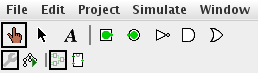
The ‘hand’ tool (leftmost on the toolbar) allows you to turn inputs on and off. The ‘arrow’ tool (next to it) allows you to place components onto the grid, move them around, and wire them together.
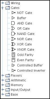
In the side-bar, the main components we’ll be using are in the Gates section, but there’s also the Pin (under Wiring) and the LED (under Input/Output).
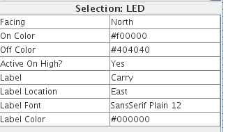
When you have a component selected, its properties appear in the lower left of the screen. You can use these to create a label for your pins and LEDs.
Circuit 1: Gray code
Try to design a circuit that converts 4-bit Gray code (the uniform-change code we experimented with in assignment 1) to standard binary. Below is a table containing corresponding numbers in each code.
 Gray Code        Binary
 G3 G2 G1 G0    B3 B2 B1 B0
  0  0  0  0     0  0  0  0
  0  0  0  1     0  0  0  1
  0  0  1  1     0  0  1  0
  0  0  1  0     0  0  1  1
  0  1  1  0     0  1  0  0
  0  1  1  1     0  1  0  1
  0  1  0  1     0  1  1  0
  0  1  0  0     0  1  1  1
  1  1  0  0     1  0  0  0
  1  1  0  1     1  0  0  1
  1  1  1  1     1  0  1  0
  1  1  1  0     1  0  1  1
  1  0  1  0     1  1  0  0
  1  0  1  1     1  1  0  1
  1  0  0  1     1  1  1  0
  1  0  0  0     1  1  1  1
The circuit can be created using just XOR gates. Label your pins and LEDs. The formulas for this are as follows:
- B3 = G3
- B2 = B3 ⊕ G2
- B1 = B2 ⊕ G1
- B0 = B1 ⊕ G0
Test and save your circuit file.
Circuit 2: Two-bit adder
Create a circuit that adds two 2-bit numbers. It will have four inputs, and three outputs. It works by feeding a half-adder into a full-adder (book pages 105–106).
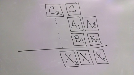
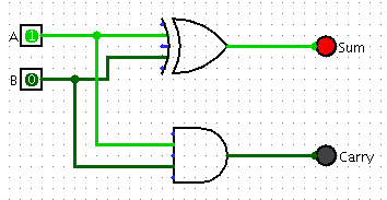
A half-adder
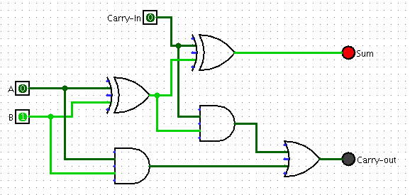
A full-adder
How to submit
You may attach both circuit files in an email to me at . Include the names of your group in the body of the email, and/or in a text box above the circuit itself.